- 您现在的位置:买卖IC网 > Sheet目录1201 > CDB5467U (Cirrus Logic Inc)BOARD EVAL FOR CS5467 ADC
�� �
�
�CS5467�
�E3MODE[1:0]� in� the� Modes� register� when� E1MODE� is�
�not� enabled.�
�6.8� No� Load� Threshold�
�The� No� Load� Threshold� register� (� Load� MIN� )� is� used� to�
�E3MODE1�
�0�
�0�
�1�
�1�
�E3MODE0�
�0�
�1�
�0�
�1�
�E3� output�
�Total� Reactive� Energy�
�Power� Fail� Monitor�
�Voltage1� Sign�
�Total� Apparent� Energy�
�zero� out� the� contents� of� E� PULSE� and� Q� PULSE� registers� if�
�their� magnitude� is� less� than� the� Load� MIN� register� value.�
�6.9� Energy� Pulse� Width�
�Note:� Energy� Pulse� Width� (� PulseWidth� )� only� applies� to�
�E1,� E2,� or� E3� pins� that� are� configured� to� output� pulses.�
�When� any� are� configured� to� output� steady-state� signals,�
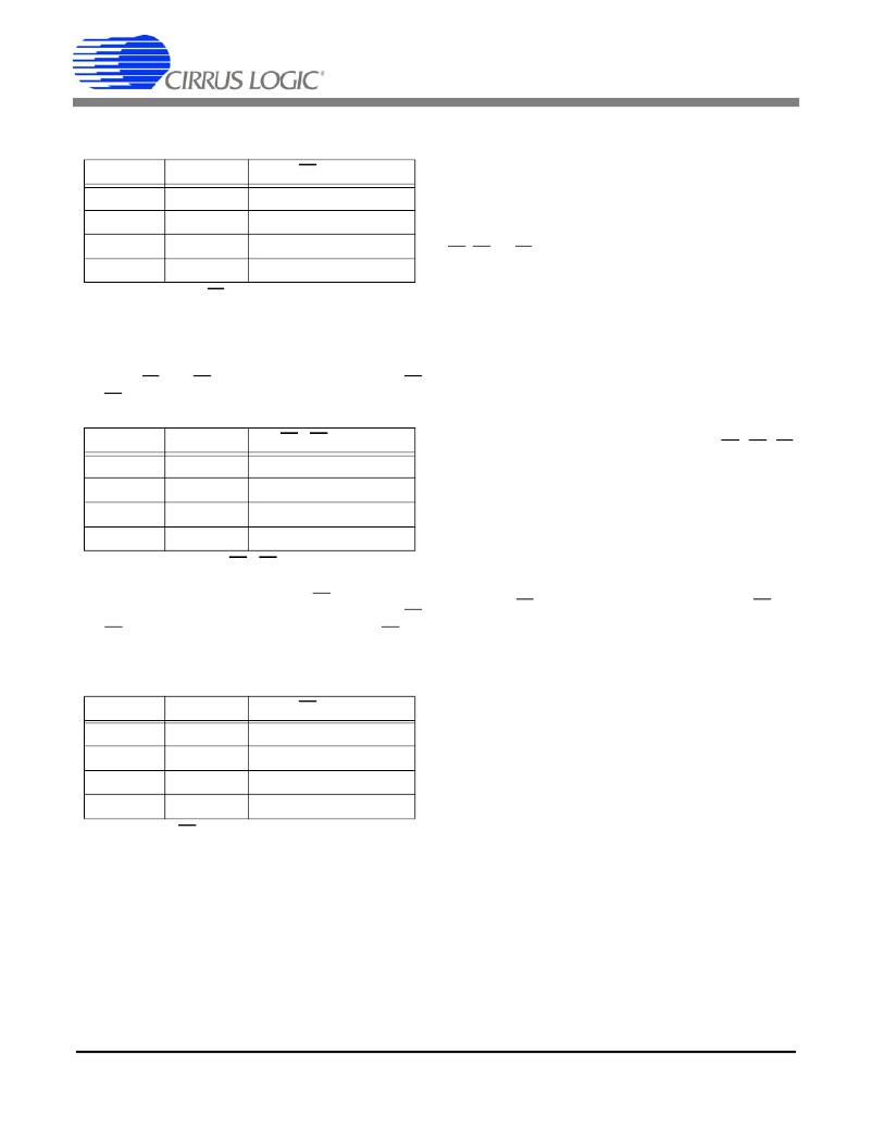
�Table� 5.� E3� Pin� Configuration�
�When� both� E2MODE� bits� are� high,� the� E1MODE� bits�
�are� enabled,� allowing� active,� apparent,� reactive,� or� wide�
�band� reactive� energy� for� both� energy� channels� to� be�
�output� on� E1� and� E2.� Table� 6� lists� the� functions� of� E1�
�and� E2� with� E1MODE� enabled.�
�such� as� voltage1� sign,� power� fail� monitor,� or� energy�
�sign,� pulse� widths� and� output� rates� do� not� apply.�
�The� pulse� width� time� (t� pw� )� in� Figure� 2� ,� is� set� by� the� value�
�in� the� PulseWidth� register� which� is� an� integer� multiple� of�
�the� sample� or� output� word� rate� (OWR).� At� OWR� of�
�4000� Hz� (a� period� of� 250� uS)� t� pw� =� PulseWidth� x�
�250� uS.� By� default,� PulseWidth� is� set� to� 1.�
�6.10� Energy� Pulse� Rate�
�E1MODE1�
�0�
�0�
�1�
�1�
�E1MODE0�
�0�
�1�
�0�
�1�
�E1� /� E2� outputs�
�Active� Energy�
�Apparent� Energy�
�Reactive� Energy�
�Wideband� Reactive�
�The� full-scale� pulse� frequency� of� enabled� E1,� E2,� E3�
�pins� is� the� value� in� PulseRate� x� output� word� rate�
�(OWR)/2.� The� actual� pulse� frequency� is� the� full-scale�
�pulse� frequency� multiplied� by� the� pulse� register’s�
�(� E� PULSE� ,� S� PULSE� ,� or� Q� PULSE� )� value.�
�Example:�
�Table� 6.� E1� /� E2� Modes�
�When� E1MODE� bits� are� enabled,� the� E3� pin� outputs� ei-�
�ther� th� e� power� fail� monitor� status,� or� the� sign� of� the� E1�
�and� E2� outputs.� Table� 7� list� the� functions� of� the� E3� pin�
�using� E3MODE[1:0]� in� the� Modes� register� when�
�E1MODE� is� enabled� .�
�If� the� output� word� rate� (OWR)� is� 4000� Hz,� and� the�
�PulseRate� register� is� set� to� 0.05,� the� full-rate� pulse� fre-�
�quency� is� 0.05� x� 4000� /� 2� =� 100� Hz.� If� the� E� PULSE� regis-�
�ter,� driving� E1,� is� 0.4567,� the� pulse� output� rate� on� E1� will�
�be� 100� Hz� x� 0.4567� =� 45.67� Hz.�
�6.11� Voltage� Sag/Current� Fault� Detection�
�Voltage� sag� detection� is� used� to� determine� when� aver-�
�aged� voltage� falls� below� a� predetermined� level� for� a�
�E3MODE1�
�0�
�0�
�1�
�1�
�E3MODE0�
�0�
�1�
�0�
�1�
�E3� output�
�Power� Fail� Monitor�
�Energy� Sign�
�not� used�
�not� used�
�specified� interval� of� time.� Current� fault� detection� deter-�
�mines� when� averaged� current� falls� below� a� predeter-�
�mined� level� for� a� specified� interval� of� time.�
�The� specified� interval� of� time� (duration)� is� set� by� the� val-�
�ue� in� the� V1Sag� DUR� (� V2Sag� DUR� )� and� I1Fault� DUR�
�(� I2Fault� DUR� )� registers.� Setting� any� of� these� to� zero� (de-�
�fault)� disables� the� detect� feature� for� the� given� channel.�
�Table� 7.� E3� Pin� with� E1MODE� enabled�
�The� value� is� in� output� word� rate� (OWR)� samples.� The�
�predetermined� level� is� set� by� the� values� in� the�
�V1Sag� LEVEL�
�(� V2Sag� LEVEL� )� and�
�I1Fault� LEVEL�
�(� I2Fault� LEVEL� )� registers.�
�DS714F3�
�21�
�发布紧急采购,3分钟左右您将得到回复。
相关PDF资料
CDB5560-2
DEV BOARD FOR CS5560 W/SE INPUT
CDB5571-2
DEV BOARD FOR CS5571 W/SE INPUT
CDB8422
BOARD EVAL FOR CS8422 RCVR
CDB8952T
BOARD EVAL FOR CS8952
CDCE906-706PERFEVM
EVAL MOD PERFORMANCE CDCE906/706
CEVAL-033
BOARD EVAL FOR CVCO33 .3"X.3"
CF37S
COVER FLANGE 37POS FEMALE
CG0402MLC-05LG
SUPPRESSOR ESD 5VDC 0402 SMD
相关代理商/技术参数
CDB5471
制造商:Cirrus Logic 功能描述:Tools Development kit Kit Con
CDB5480U-Z
功能描述:电源管理IC开发工具 CS5480 Eval Board
RoHS:否 制造商:Maxim Integrated 产品:Evaluation Kits 类型:Battery Management 工具用于评估:MAX17710GB 输入电压: 输出电压:1.8 V
CDB5484U-Z
功能描述:电源管理IC开发工具 CS5484 Eval Board
RoHS:否 制造商:Maxim Integrated 产品:Evaluation Kits 类型:Battery Management 工具用于评估:MAX17710GB 输入电压: 输出电压:1.8 V
CDB5490U-Z
功能描述:电源管理IC开发工具 CS5490 Eval Board
RoHS:否 制造商:Maxim Integrated 产品:Evaluation Kits 类型:Battery Management 工具用于评估:MAX17710GB 输入电压: 输出电压:1.8 V
CDB5501
制造商:Cirrus Logic 功能描述:EVAL BOARD FOR CS5501 - Bulk
CDB5503
制造商:Cirrus Logic 功能描述:EVAL BOARD FOR CS5503 - Bulk
CDB5504
制造商:CIRRUS 制造商全称:Cirrus Logic 功能描述:Low Power, 20-Bit A/D Converter
CDB5505
制造商:Cirrus Logic 功能描述:EVAL BD FOR CS5505 - Bulk